
🎯Quick Answer: The Four Numbers
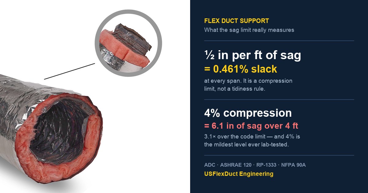
Support horizontal flexible duct at no more than 4-foot intervals, stabilize vertical duct at no more than 6 feet on center, keep sag under ½ inch per foot of spacing, and never let anything narrower than 1½ inches touch the duct. A connection to rigid duct or equipment counts as a support joint. The sag limit is the important one and it is widely misread as a cosmetic standard: ½ inch per foot works out to 0.461% of longitudinal slack at any span, which means a duct sagging at exactly the code limit is within half a percent of fully stretched. Every compression level ever put through an ASHRAE 120 test rig — starting at the mildest, 4% — produces three times the allowable sag or more. The rule is strict, it costs three dollars and four minutes to verify, and almost nobody verifies it.
We manufacture flexible duct, which means we get the phone call after the balance report comes back short. The branch was sized correctly. The equipment is the right tonnage. The duct is the right diameter and the right R-value, and it is delivering maybe two-thirds of the design airflow.
Nine times out of ten, nobody did anything an inspector would write up. The duct was cut a little long, hung a little loose, and allowed to swag between joists — which is to say, it was installed the way flexible duct is installed on most job sites in America. The performance loss from that is not a rounding error. It is the single largest, cheapest-to-fix variable in a residential or light commercial air distribution system, and it is governed entirely by where you put the hangers.
This guide takes the four support numbers everyone can recite, converts them into the compression numbers nobody quotes, and shows why the two most authoritative sources on the subject disagree by a factor of 2.5.
The Four Support Numbers, and Where They Come From
Flexible duct support is one of the few areas of mechanical work where the model code largely declines to write the rule itself. The code defers to the manufacturer's installation instructions, and the manufacturer's installation instructions reproduce, nearly verbatim, the Air Diffusion Council's Flexible Duct Performance and Installation Standards. So the operative text is the same sheet of paper that comes in the carton.
| Requirement | The number | Source text |
|---|---|---|
| Horizontal support interval | ≤ 4 ft | "supported at manufacturer's recommended intervals, but at no greater distance than four feet" |
| Maximum sag | ≤ ½ in per ft of spacing | "Maximum permissible sag is 1/2 inch per foot of spacing between supports" |
| Minimum contact width | ≥ 1½ in | "In no case will the material contacting the flexible duct be less than 1-1/2 inch wide" |
| Vertical stabilization | ≤ 6 ft on center | "Vertically installed duct shall be stabilized by support straps at a maximum of 6 feet on center" |
| What counts as a support | Collars count | "A connection to rigid ducting or equipment shall be considered a support joint" |
| Hanger function test | No ID restriction | "of sufficient width to prevent any restriction of the internal diameter of the duct when the weight of supported section rests on the hanger" |
| Installed condition | Fully extended | "Install duct fully extended, do not install in the compressed state or use excess lengths" |
You will also encounter 5 feet in circulation, including in the US Department of Energy's Building America Solution Center, whose flex duct guidance is titled around installing supports every 5 feet. Some SMACNA-derived contractor guidance quotes 4 to 6 feet. These are not competing legal standards; they are field guidance written at different levels of strictness. The binding number on your job is whichever the authority having jurisdiction adopted, and the manufacturer's instruction sheet, whenever the instruction sheet is stricter — which it usually is. Ours says four feet.
⚠️The support you forget is the one at the collar
"A connection to rigid ducting or equipment shall be considered a support joint" is doing more work than it appears to. It means the run is measured from the collar, not from the first strap you happened to install. A branch that leaves a plenum and gets its first hanger at 6 feet is non-compliant even if every subsequent strap is at 4-foot centers — and the first span off a collar is exactly where slack accumulates, because that is where the installer was working with an uncut coil.
The Sag Limit Is a Compression Limit in Disguise
Here is the part that is missing from every version of this article we could find. The sag rule is written in inches, and the performance research is written in percent compression, and nobody publishes the conversion between them — even though it is a one-line piece of geometry.
A duct hanging under its own weight between two supports takes the shape of a shallow cable. If the span is L and the deepest sag is s, the length of duct in that span exceeds L by a predictable amount. Running that arithmetic on the code limit produces a result worth pinning to the wall:
💡½ inch per foot = 0.461% longitudinal slack — at every span
Because the limit is expressed per foot of spacing, the ratio of sag to span is fixed at 1:24 no matter how far apart the hangers are. A 4-foot span at 2 inches of sag, a 5-foot span at 2.5 inches, a 24-inch joist bay at 1 inch — all three contain exactly 0.461% more duct than the straight-line distance. The rule is scale-free by construction. Whoever wrote it in that form understood they were writing a compression limit, not a geometry preference.
Read the other direction, that number is a useful shock. Half a percent. The compliant duct is, for all practical purposes, taut. Anything you would describe in plain English as "a little loose" is already out of tolerance by a wide margin, and the following table shows how wide.
| Longitudinal compression | Excess duct (slack) | Sag over a 4 ft span | Sag over a 5 ft span | vs ½ in/ft limit |
|---|---|---|---|---|
| 0.46% (the code limit) | 0.46% | 2.0 in | 2.5 in | Pass (at limit) |
| 4% | 4.2% | 6.1 in | 7.6 in | 3.1x over |
| 10% | 11.1% | 10.3 in | 12.8 in | 5.1x over |
| 15% | 17.6% | 13.3 in | 16.6 in | 6.6x over |
| 30% | 42.9% | 22.4 in | 28.0 in | 11x over |
| 45% | 81.8% | 34.1 in | 42.7 in | 17x over |
Sag figures are the geometric maximum for a uniformly loaded shallow cable — the sag you would see if all of the slack resolved into a single clean curve in the vertical plane. Real ducts do not manage that, which turns out to matter a great deal; see the section on why the tape measure reads low.
The practical consequence is that the sag rule, honestly enforced, would eliminate the entire compression problem the research documents. The mildest compression level anyone has bothered to test in a laboratory is 4%, and 4% compression puts a 4-foot span more than three times over the limit. There is no overlap between "passes the sag inspection" and "is compressed enough to matter." The industry does not have a knowledge gap here. It has an enforcement gap, and the enforcement tool is a tape measure.
What Compression Costs — and Two Sources That Disagree
Now the other half of the conversion. What does compression actually do to airflow? There are three widely cited answers and they do not agree, which is itself the most useful thing about them.
| Source | 15% compression | 30% compression | 45% compression |
|---|---|---|---|
| Air Diffusion Council teaching material the trade association's own chart | ~2x pressure drop | ~4x | ~6–8x |
| Abushakra, Walker & Sherman LBNL, 6/8/10 in, ASHRAE 120-1999 | "moderate compression, typical of that often seen in field installations, could increase the pressure drop by a factor of four" | "factors close to ten" | |
| Culp, ASHRAE RP-1333 6/8/10 in, ANSI/ASHRAE 120 | above 15% compression, loss "can exceed ten times" fully stretched duct of the same diameter; data ran higher than prior ACCA and ASHRAE figures | ||
Put the 30% column side by side and the gap is the story. The trade association says four times. The laboratory says the four-times figure describes ordinary field compression, and that 30% is closer to ten. That is a factor of roughly 2.5 between the number printed on the installation poster and the number measured on a test rig built to ASHRAE Standard 120.
The LBNL team did not leave this to inference. Their stated conclusion was that "the available published references tend to underestimate the effects of compression." Culp's RP-1333 data likewise came in above the prior ACCA and ASHRAE figures. Two independent research efforts, a decade apart, both landed on the same verdict about the industry's own numbers.
ℹ️Why a manufacturer is telling you this
The optimistic chart is our industry's chart, and we would rather you design against the pessimistic one. A duct designer who sizes a branch using a 2x friction-rate penalty at 15% compression, on a run that is actually compressed and actually loses 4x or more, has produced a system that is short on airflow on the day it is commissioned and has no headroom left anywhere. We sell more duct when systems are designed with realistic assumptions, not fewer — undersized branches get rebuilt, and rebuilt branches are somebody's warranty problem, usually the contractor's.
Bends compound this. The ADC's own equivalent-length figures put a 90-degree bend in flexible duct at roughly 20 equivalent feet and a 45-degree bend at about 10 equivalent feet, before any compression penalty is applied to the straight sections. A 20-foot run with two 90s and 15% compression is not a 20-foot run in any sense that matters to the blower. If you are sizing branches, do it on total equivalent length using our flex duct CFM chart and the duct sizing guide, not on the tape measure distance from plenum to boot.
Every Lab Compression Level Fails the Sag Rule
Merging the two halves gives the table this article exists to publish. Left column: what the researchers tested. Right column: what that condition would have looked like to an inspector with a tape measure.
| Condition | Pressure drop vs stretched | Geometric sag, 4 ft span | Sag inspection |
|---|---|---|---|
| Fully extended | 1.0x (baseline) | 0 in | Pass |
| Code limit, ½ in/ft | ≈1.0x | 2.0 in | Pass |
| 4% compression | Measurably higher; flex at ~70 cfm where rigid delivers ~110 cfm at 0.1 in w.c. | 6.1 in | Fail, 3.1x |
| 15% compression | 2x (ADC) to >10x (RP-1333) | 13.3 in | Fail, 6.6x |
| 30% compression | 4x (ADC) to ~10x (LBNL) | 22.4 in | Fail, 11x |
| 45% compression | 6–8x (ADC); measured curves run to several in w.c. | 34.1 in | Fail, 17x |
There is no row in that table where a duct is compressed enough to hurt and still passes the sag check. That is not a coincidence; it is the rule doing its job. It is also why the sag limit is the single most valuable line on a mechanical punch list and one of the least frequently measured.
Request a Quote for flexible duct, hanger strap and installation accessories
Fill in your requirements. We respond within 24 hours on business days.
Why the Tape Measure Reads Low, and Gets Worse With Age
The geometric sag figures above assume every inch of slack resolves into one clean vertical curve. Real flexible duct does not cooperate. Some of the excess goes sideways as lateral snaking, some of it bunches at the spiral wire, and some of it forms local kinks near the supports. So the sag you can measure is always less than the geometry says it should be for the amount of slack present.
Weaver and Culp at Texas A&M measured this directly, on 6, 8 and 10 inch duct laid across joists at 24 inches on centre. For 6-inch duct at 45% compression, they recorded roughly 7 inches of natural sag immediately after installation, and 11.5 inches of long-term sag after the duct had been left to relax. The geometric maximum for 45% compression over a 24-inch span is 17.1 inches. Inverting their measurements through the same cable geometry gives the number that should change how you read a job site:
| 6 in duct, 45% compressed, 24 in joist spacing | Sag | Compression a tape measure would report | Under-reporting |
|---|---|---|---|
| Geometric maximum | 17.1 in | 45% (true value) | — |
| Measured, natural sag (day one) | 7.0 in | 16.3% | 2.8x optimistic |
| Measured, long-term sag | 11.5 in | 30.9% | 1.5x optimistic |
Two conclusions fall out of those three rows, and both of them argue for hanging duct tighter than code requires.
- Sag under-reports compression, so the inspection is generous to the installer. A duct that is genuinely 45% compressed looked, on day one, like a duct 16% compressed. If a run barely passes your sag check, the actual amount of surplus duct in it is larger than the tape measure suggests, not smaller. There is no version of this error that flatters the buyer.
- Sag grows over time, toward the geometric limit. The same duct went from 7 inches to 11.5 inches with nothing changed but time. Flexible duct creeps: the jacket relaxes, the insulation settles, the helix works loose from the framing. The sag measured at rough-in inspection is the best that run will ever look. A duct passing at exactly 2 inches on a 4-foot span in March is not necessarily passing in October, and nobody goes back into the attic to check.
⚠️Design margin, not code minimum
This is the engineering reason we tell customers to hang at 3-foot intervals on runs longer than 15 feet, and to order duct cut to length rather than pulling from a coil in the attic. Code minimum plus creep equals eventual non-compliance. Code minimum minus 25% equals a system that still performs in year five. The cost difference is a handful of straps and about ten minutes per branch.
The Strap Itself: Width, Material, Fire Rating
Spacing gets all the attention. The strap gets almost none, which is odd given that the strap is the only part of this that anyone has to buy.
Width: 1½ inches is a floor, not a target
The standard's wording has two halves and most people only quote the second. The functional requirement comes first — the hanger or saddle must be "of sufficient width to prevent any restriction of the internal diameter of the duct when the weight of supported section rests on" it — and the 1½ inch figure is the backstop: "in no case will the material contacting the flexible duct be less than 1-1/2 inch wide."
On 6-inch bare or lightly insulated duct, 1½ inches satisfies both halves. On 16, 18 and 20-inch R-8 duct, the weight per foot is several times higher and the insulation is three inches thick; 1½ inches of nylon carrying that load will dish the jacket and squeeze the core. Use 2 to 3 inch strap or a formed saddle that cradles the lower third of the circumference. The test is the functional one: after the duct is resting on it, is the inner core still round?
| Duct | Minimum legal contact width | What we recommend |
|---|---|---|
| 4–8 in, bare or R-4.2 | 1½ in | 1½ in strap |
| 10–14 in, R-6 / R-8 | 1½ in | 2 in strap |
| 16–20 in, R-8 | 1½ in | 3 in strap or formed saddle |
| Any size, wire or zip tie | Not permitted | Never — cuts jacket, crushes core |
Fire rating: the requirement nobody checks
This one catches people. Under NFPA 90A and 90B, supplementary materials used with air ducts must meet Class 1 when tested to UL 723 — flame spread index 25 or less, smoke developed index 50 or less. A hanger strap in a plenum or attic is supplementary material.
Contractors buy UL 181B-FX tape without a second thought because the marking is printed on the roll and inspectors look for it. Nobody looks at the strap. Pallet banding, generic polypropylene webbing and hardware-store nylon will all hold a duct and none of them necessarily carries a 25/50 rating. If your submittal lists the tape, the mastic and the clamps but not the hanger strap, you have an undocumented combustible running the length of every branch. Our duct sealing guide covers the UL 181A and 181B closure markings for the rest of that kit.
Where the 4-Foot Rule Does Not Tell You to Put a Hanger
The interval rule covers straight, uneventful duct. Four situations need a hanger the interval will never ask for, and all four come straight out of the manufacturer instruction sheets.
- Before and after every sharp bend, approximately one duct diameter back from the centerline of the bend on each side. Bends are where slack migrates and where equivalent length is already costing you 10 to 20 feet apiece. An unsupported bend also tends to tighten below the minimum radius, which is one duct diameter at the centerline — see the flex duct installation guide for the bend radius detail.
- Immediately out of every sheet metal collar. Let the duct run straight for a few inches before it turns. Without that, the cut edge of the collar works against the jacket every time the system cycles, and you eventually get a vapor barrier tear that nobody finds. Collar and sleeve dimensions are in the duct connector guide.
- Anywhere the duct would bear on a hard edge — pipes, conduit, truss plates, strapping, the corner of a junction box. Incidental contact with metal fixtures is called out as a thing to avoid, not a thing to accept.
- At terminal devices. Registers, boots and diffusers must be supported independently of the flexible duct. Hanging a boot from the duct loads the last span with the weight of the fitting and guarantees sag exactly where the run needs to be straight. The duct boot guide covers boot support and sizing.
Duct resting on ceiling joists or truss supports is explicitly permitted, and it is how a large fraction of residential flex is actually installed. The rules do not change: bearing points must fall inside the maximum spacing, and the top edge of a nominal joist gives you exactly 1½ inches of bearing — the legal minimum and nothing more. Over 24-inch centers, that is fine for small bare duct. For large insulated duct, run a board or a saddle across two joists rather than letting three inches of fiberglass bridge a 22½-inch gap with its whole weight on two 1½-inch edges.
The Other Number Geometry Eats: Installed R-Value
Compression is not the only thing about flexible duct that performs differently than the label implies, and support hardware sits directly on the second one.
Nominal flex duct R-values are measured with the insulation flat. Installed, that blanket is wrapped into a cylinder, so the outer layers are stretched thinner relative to the inner surface area they are protecting. Work presented at the ACEEE Summer Study on Energy Efficiency in Buildings quantified the gap across the full size range:
| Nominal duct dia. | Nominal R-6 → actual total | Nominal R-8 → actual total | Nominal R-11 → actual total |
|---|---|---|---|
| 4 in | R-4.85 | R-5.69 | R-6.76 (61% of rating) |
| 6 in | R-5.40 | R-6.45 (19% low) | R-7.81 (29% low) |
| 8 in | R-5.76 | R-6.94 | R-8.52 |
| 12 in | R-6.18 | R-7.56 | R-9.43 |
| 20 in | R-6.61 | R-8.18 | R-10.38 (94% of rating) |
Totals include internal film resistance and R-0.667 external film, for R-2.8 per inch insulation at 500 fpm, no diameter oversize. The penalty is a pure geometry effect and it shrinks as diameter grows — small ducts with thick blankets are hit hardest, which is exactly the combination a code official is most likely to require.
That is the loss you inherit. The loss you cause is mechanical. Every narrow strap, every wire tie and every joist edge compresses the blanket locally, and compressed fiberglass is not insulation. California's energy code already assumes duct wrap goes in at 75% of nominal thickness — a 25% haircut before anyone does anything wrong. A 1-inch strap cinched down over R-8 does far worse than 25% at the contact point, and it does it at regular 4-foot intervals along a run sitting in a 130 °F attic.
If you are choosing an R-value for an unconditioned space, read our R6 vs R8 comparison and the R4 vs R6 vs R8 breakdown with these numbers in hand — and know that wide straps are part of the R-value decision, not a separate line item. The attic duct insulation guide covers the ambient conditions that make it matter.
A Four-Minute Tape-Measure Inspection
No gauges, no manometer, no training. Walk the run and take four measurements.
| Measure | Accept | Reject | What rejection means |
|---|---|---|---|
| Longest gap between bearing points | ≤ 48 in | > 48 in | Add a strap. Count the collar as a support. |
| Deepest sag ÷ span in feet | ≤ 0.5 in/ft | > 0.5 in/ft | Surplus duct in the run. Cut it out — do not just add hangers. |
| Strap contact width | ≥ 1.5 in | < 1.5 in, or wire | Replace. Check the jacket underneath for cuts. |
| Lateral snaking, sighting down the run | Straight | Visible S-curves | Slack hiding sideways. Sag reading is understating compression. |
💡The fix for failed sag is scissors, not straps
Adding hangers to a run with surplus duct in it redistributes the sag into shorter, deeper bays and leaves the compression exactly where it was — the duct is still 15% too long for the distance it spans. The only correct remedy is to shorten the run: pull it taut, cut the excess, and remake the connection. That is a five-minute job at rough-in and a two-hour job after drywall, which is the entire argument for measuring during rough-in.
Spec Language You Can Copy
Most mechanical specifications we are quoted against say "flexible duct shall be supported per manufacturer's instructions." That sentence delegates the whole problem to the installer and gives you nothing to enforce at punch list. Here is language that does.
💡Suggested specification text
"Flexible duct shall be installed fully extended. Longitudinal compression shall not exceed 2% of the manufactured length in any run. Horizontal supports shall be spaced at not more than 4 feet on center, and at not more than 3 feet on center for runs exceeding 15 feet; a connection to rigid duct or equipment shall be counted as a support joint. Sag between supports shall not exceed ½ inch per foot of spacing, verified by measurement at rough-in. Hanger or saddle material in contact with the duct shall be not less than 1½ inches wide for duct up to 14 inches diameter and not less than 3 inches wide, or a formed saddle, above 14 inches. Wire and cable ties are not acceptable as duct supports. Hanger material shall be listed or documented as Class 1 to UL 723 (flame spread ≤ 25, smoke developed ≤ 50) per NFPA 90A/90B. Additional supports shall be provided one duct diameter each side of every bend, at every sheet metal collar, and wherever the duct would otherwise bear on a pipe, conduit or framing edge. Terminal devices shall be supported independently of the flexible duct. Branch sizing shall be based on total equivalent length including 20 equivalent feet per 90-degree bend and 10 equivalent feet per 45-degree bend."
Every clause in that paragraph traces back to a document quoted on this page. The only additions beyond the published minimums are the 2% compression cap, the 3-foot interval on long runs and the 3-inch strap above 14 inches — the three places where, having read the creep data, we think the published minimum is too thin to survive a decade in an attic.
What We Ship, and a Correction to Our Own Catalog
We manufacture and stock flexible duct, insulated duct and industrial hose from a 46,000 sq ft facility in Brookshire, Texas, and we sell the hanger strap alongside the duct because the two are one purchasing decision, not two.
⚠️We got two numbers wrong on our own product page
Writing this article sent us back to our own catalog, where the duct hanger listing carried a 1-inch strap width and the line "spacing: every 5 ft per code." Both are wrong by the standard quoted throughout this page: the contact material may never be under 1½ inches, and the horizontal interval is 4 feet, not 5. We have corrected the listing. We are leaving this note here rather than quietly editing it, because a supplier who publishes a below-minimum strap width is exactly the supplier this article is warning you about, and the honest response to finding yourself in your own cautionary example is to say so.
What we ask for on a hanger enquiry, and what we will put in writing on the quote:
- Duct diameters and R-values in the run — this sets strap width, because weight per foot drives the crush risk more than diameter alone.
- Total linear feet of duct and the number of branches — one strap per 4 feet per branch plus two per bend plus one per collar is the real count, and it is usually 30–40% more strap than people order.
- Whether the run is in a plenum or return air space — this decides whether the UL 723 Class 1 documentation needs to go on the submittal.
- Cut lengths. We will supply duct cut to length. It costs a little more per foot and it removes the single mechanism by which compression enters a job — an installer holding a coil and estimating.
MOQ is flexible on accessories ordered with duct, and we quote factory-direct on full-pallet and container volumes. Browse the flexible duct range, the R4.2, R6 and R8 insulated duct, or the full duct accessories line.
Frequently Asked Questions
Frequently Asked Questions
How far apart should flex duct hangers be?
How much sag is allowed in flexible duct?
How wide do flex duct hanger straps need to be?
Does sagging flex duct really reduce airflow that much?
Can flex duct rest on ceiling joists instead of hanging from straps?
Where do I need extra hangers beyond the 4-foot rule?
What fire rating does a duct hanger strap need?
Does compressed flex duct also lose R-value?
How do I inspect flex duct support without special tools?
Sources
- Air Diffusion Council, Flexible Duct Performance & Installation Standards, and ADC installation training material — support intervals, sag limit, 1½ in contact width, longitudinal compression pressure-drop multipliers (15% ≈ 2x, 30% ≈ 4x, 45% ≈ 6–8x), bend equivalent lengths (90° = 20 ft, 45° = 10 ft), NFPA 90A/90B and UL 723 Class 1 requirement for supplementary materials.
- Manufacturer installation instructions for UL 181 listed nonmetallic air ducts and air connectors (Builders Best, UL File MH9596/9844) — verbatim support, sag, collar, bend and terminal-device clauses.
- B. Abushakra, I. S. Walker and M. H. Sherman, Compression Effects on Pressure Loss in Flexible HVAC Ducts, Lawrence Berkeley National Laboratory — 6, 8 and 10 in duct tested to ASHRAE Standard 120-1999; factor-of-four and near-tenfold findings; conclusion that published references underestimate compression effects.
- C. Culp, HVAC Flexible Duct Pressure Loss Measurements, ASHRAE Research Project RP-1333 final report, 2011 — compression levels 0%, 4%, 15%, 30%, 45%; losses above 15% compression exceeding ten times fully stretched duct.
- K. Weaver and C. Culp, Static Pressure Losses in 6, 8 and 10-inch Non-Metallic Flexible Ducts, Texas A&M University — natural and long-term sag measurements over 24 in joist spacing, as reported and charted by Energy Vanguard, "The Science of Sag."
- True R-Values of Round Residential Ductwork, ACEEE Summer Study on Energy Efficiency in Buildings, 2006 — Table 1, actual versus nominal R-values by diameter for R-4.2, R-6, R-8 and R-11 flexible duct.
- US DOE Building America Solution Center, Support at Intervals for Flex Ducts — the 5-foot interval guidance noted above.
- California Title 24 duct insulation provisions — installed thickness assumed at 75% of nominal.
- Sag-to-slack conversions and the inversion of the Weaver & Culp sag measurements are our own calculation, using standard shallow-cable arc-length geometry. Figures are geometric maxima; see the discussion of why measured sag runs lower.
Related Guides
- Flex Duct Installation Guide: Cutting, Connecting & Bend Radius
- Flex Duct Sizes Guide: Diameters, CFM & Selection
- Flex Duct CFM Chart: Airflow by Diameter and Friction Rate
- R6 vs R8 Duct Insulation: Which R-Value Do You Need?
- UL 181 Class 1: Air Duct vs Air Connector and the 14-Foot Rule
- Duct Connector Guide: Collars, Sleeves & Clamps
- Duct Fittings Guide: Types, Sizes & Equivalent Length
- Flex Duct vs Metal Duct: Cost, Airflow & Code Comparison
- Duct Hangers & Straps: Galvanized and Nylon
- Insulated Flexible Duct: R4.2, R6 and R8
Request a Quote for flexible duct, hanger strap and installation accessories
Fill in your requirements. We respond within 24 hours on business days.